Configuring Network Connection
Connecting to the router
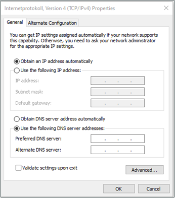
Step 1: By default, the IP address of WAN/LAN on TK600 is 192.168.1.1; the IP address of LAN on TK600 is 192.168.2.1. This document uses the LAN port to access the TK600 as an example. Set the PCs IP address to be on the same subnet with LAN.
Method 1: Obtain an IP address automatically (recommended)
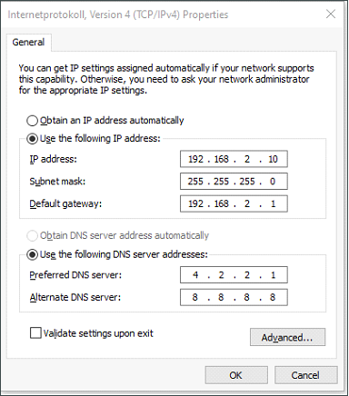
Method 2: Set a fixed IP address
Select Use the following IP address, enter an IP address (By default, any from 192.168.2.2 to 192.168.2.254), subnet mask (By default,255.255.255.0), default gateway (By default,192.168.2.1), and DNS server address, and click OK.
Logging in to the router
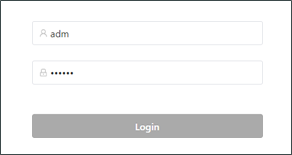
Connect the PC to the router directly by using the network cable, start the web browser, enter https://192.168.2.1 in the address bar, and press Enter to jump to the web login page. Enter the username (default: adm) and password (default: 123456), and click OK or press Enter to access the web configuration page.
Navigation Bar Operations
Returning to the Homepage
You can click the Welotec logo in the upper left corner of any web page of the TK600 to return to the Overview page quickly.

Logging Out

To log out from the TK600, click the user name in the upper right corner.
Overview
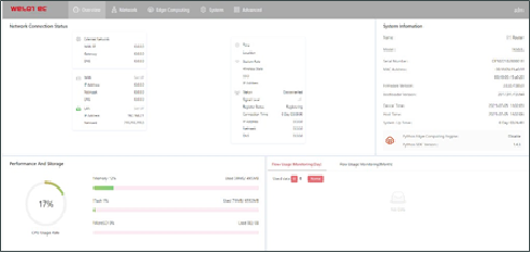
The Overview page displays information about the TK600, such as its network connection status, system information, and data usage. You can quickly obtain the TK600 running status on this page after you log in to the TK600 web page, the Overview page appears by default. You can also click Overview to display this page. This page displays the following information:
Network Connection Status: shows the TK600s network connection status and network configuration.
Network
Network interface
Cellular
The Cellular page displays the configuration and status of the TK600 dial-up interface. You can set dial-up interface parameters to connect the TK600 to a cellular network or view details about the dial-up interface on this page. Follow these steps to configure the dial-up interface:
Choose Network > Network Interfaces > Cellular to display the Cellular page.
Select Enable Cellular.
Set the parameters (default settings recommended).
Click Submit to complete the configuration of the dial-up interface. The cellular network parameters are described as follows:
Enable Cellular: enables or disables the cellular network connection.
Profile
Network Type: specifies the type of the mobile network to which the router is connected, which can be GSM or CDMA.
APN: specifies the access point name (APN) that identifies the service type of a WCDMA/LTE network. A WCDMA/LTE system provides services based on the APN of the connected WCDMA/LTE network.
Access Number: specifies the dial string provided by the network operator. Obtain this dial string from your network operator.
If your 3G/LTE data card supports WCDMA or LTE, the default dial string is *99***1#.
If your 3G data card supports CDMA 2000, the default dial string is #777.
Auth Method
Auto: selects an authentication method automatically.
PAP: specifies the Password Authentication Protocol, a simple plain-text authentication method implemented through two-way handshakes.
CHAP: specifies the Challenge Handshake Authentication Protocol, a security authentication method that verifies message digests through three-way handshakes.
MS-CHAP: specifies the CHAP standard defined by Microsoft.
MS-CHAPv2: specifies the upgraded version of MS-CHAP, which requires two-way authentication.
Username: specifies the username used for connection to the public data network (PDN). It is provided by your network operator.
Password: specifies the password of the PDN user. It is provided by your network operator. Dual SIM Enable: enables or disables the dual-SIM card mode.
Main SIM: specifies the main SIM card used. Options are SIM1, SIM2, Random, and Sequential.
Max Number Of Dial: specifies the maximum number of dial-up attempts on SIM1. When the number of dial-up failures reaches this number, the router switches to SIM2.
Min Connected Time: specifies the minimum network connection duration after the router dials up successfully. Within this duration, the number of dial-up attempts is counted. When the connection duration exceeds the set value, the number of dial-up attempts is reset. When the value is set to 0, this function is disabled.
Backup SIM Timeout: specifies the timeout period of the backup SIM card used currently. The router switches to the main SIM card when the timeout period of the backup SIM card is reached.
Network Type: specifies a network type for the SIM card. Options are Auto, 3G, 4G, and 2G. You can select a specific network type suitable for your router and SIM card or choose the auto mode, in which the router automatically registers to the suitable network.
Profile: specifies the index of the dial-up parameter set.
Roaming: enables the roaming function to allow the router to dial up in roaming state or disables the roaming function to prevent the router from dialing up in roaming state. When a local SIM card is used, its dial-up capability is not affected whether this option is selected or deselected.
PIN code: specifies the personal identification number of the SIM card. If you enable PIN code but do not set a PIN code or set a wrong PIN code, the router cannot dial up. A valid PIN code enables the router to dial up to a network.
Static IP: enables or disables the use of a static IP address. If you select this option, specify an IP address manually. Then, the router obtains the specified static IP address every time it dials up to a network.
Connection Mode
Always Online: indicates that the router stays online when it is running properly and will be disconnected and redial up only if the dial-up interface does not transmit any traffic in 30 minutes. This is the default connection mode of the system.
On-demand Dial
Data Trigger: indicates that the router is offline by default and will dial up automatically when data is sent to the Internet.
Manual Dial: indicates that the network connection can be established or terminated by clicking Connect or Disconnect in the Status area.
Redial Interval: specifies the period that the router waits before dialing up again.
ICMP Probes
ICMP Detection Server: specifies the IP address or domain name of the remote ICMP server to be probed. (If two ICMP servers are enabled, it is recommended that you enter the IP addresses or domain names of both servers here.) The router supports two ICMP servers: a primary server and a backup server. After two servers are configured, the router probes the primary server first. It probes the secondary server only when the number of probe retries on the primary server reaches the maximum value. If both the servers fail to be detected, the router dials up again and starts a new round of ICMP probe.
ICMP Detection Interval: specifies the interval between ICMP probe packets sent from the router.
ICMP Detection Timeout: specifies the timeout period of an ICMP probe. If the router does not receive any ICMP Reply packet within this period, it considers that the ICMP probe times out.
ICMP Detection Max Retries: specifies the maximum number of retries after an ICMP probe failure. (The router dials up again when the number of retries reaches this value.)
ICMP Detection Strict: enables or disables the strict ICMP probe mode. In this mode, the router does not send ICMP probe packets when its dial-up interface is transmitting data traffic. It sends ICMP probe packets only when the dial-up interface is idle.
Advanced Settings
Initial Commands: specifies some AT commands used to check the module status.
RSSI Poll Interval: specifies the interval at which the router checks the signal status after dialing up successfully. For example, the interval is set to 60s. If you remove the antennas after the router dials up successfully, the signal strength will remain unchanged in 60s and decrease 60s later. If the interval is set to 0, RSSI polling is disabled.
Dial Timeout: specifies the dial-up timeout period. If the router fails to dial up to a network within the timeout period, the dial-up times out. In this case, the router checks the module status and dials up to the network again.
MRU: specifies the maximum receive unit, which is expressed in bytes.
MTU: specifies the maximum transmit unit, which is expressed in bytes.
Use Default Asyncmap: enables or disables the default Asyncmap.
Use Peer DNS: enables or disables the use of the DNS server assigned in the connected network.
LCP Interval: specifies the interval at which the router checks whether the cellular connection is normal.
LCP Max Retries: specifies the maximum number of dial-up retries after the link connection is interrupted.
Infinitely Dial Retry: enables the router to retry unlimited times upon a dial-up failure.
Debug: enables display of more detailed system logs.
Expert Options: allows you to set command parameters.
WAN
The following figure shows the configuration of WAN/LAN, with Interface Type set to WAN.
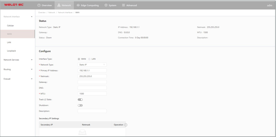
The Ethernet parameters are described as follows:
Network Type (Static IP by default)
Static IP: uses a manually configured IP address, matching subnet mask, and other information for the Ethernet interface.
Dynamic Address (DHCP): configures the interface as a DHCP client to obtain an IP address, the matching subnet mask, and other information through DHCP.
Static IP mode
Primary IP: specifies the IP address of the Ethernet interface. By default, the IP address of WAN/LAN is 192.168.1.1, and the IP address of LAN is 192.168.2.1.
Netmask: specifies the subnet mask of the Ethernet interface.
MTU: specifies the maximum transmit unit, which is expressed in bytes. The default value is 1500.
Speed/Duplex, including:
Auto Negotiation
100M Full Duplex
100M Half Duplex
10M Full Duplex
10M Half Duplex
Track L2 State: enables or disables tracking of L2 interface status. After this feature is enabled, the interface is Down when it is not physically connected and is Up when it is physically connected. After this feature is disabled, the interface state is displayed as UP regardless of whether the interface is physically connected.
Shutdown: disables the interface.
Description: specifies the descriptive information that identifies the Ethernet interface.
Secondary IP Setting: allows you to set up to 10 secondary IP addresses in addition to the primary IP address.
LAN
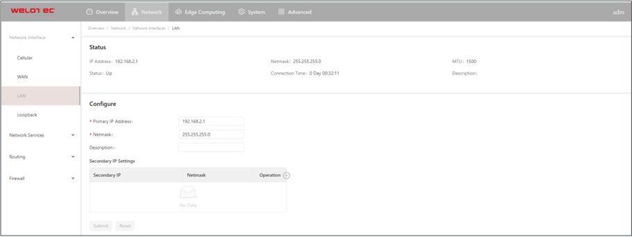
Primary IP: specifies the primary IP address of the interface.
Netmask: specifies the subnet mask of the interface.
Secondary IP Settings: allows you to set up to 10 secondary IP addresses in addition to the primary IP address.
Loopback
The loopback interface is a logical, virtual interface on the TK600. After you create and configure the loopback interface, you can ping its IP address or set up a Telnet connection to it to test the network connectivity. You can set or view loopback interface parameters on the Loopback page. Follow these steps to configure the loopback interface:
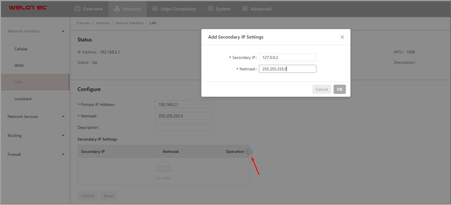
Choose Network > Network Interfaces > Loopback to display the Loopback page. You can set or view loopback interface parameters on this page.
Click the Add icon in the table under Secondary IP Settings to add a secondary IP address for the loopback interface. (The default IP address is 127.0.0.1.)
Enter the secondary IP address and subnet mask.
Click Submit to complete the configuration of the loopback interface.
As shown in the following figure, a secondary IP address 127.0.0.2 is set for the loopback interface.
Network Services
DHCP
The Dynamic Host Configuration Protocol (DHCP) uses the client/server communication model. The client sends a configuration request to the server, and the server replies with the IP address allocated to the client and other configuration information. In this way, the client IP address and other configuration is assigned dynamically. You can configure a DHCP server and view its configuration on the DHCP Server page. Follow these steps to configure a DHCP server:
Choose Network > Network Services > DHCP > DHCP Server to display the DHCP Server page.
Click the Add or Edit icon to configure the DHCP server.
Set the parameters.
Click OK to save the configuration, and then click Submit to apply the configuration. The following figure shows the DHCP server configuration.
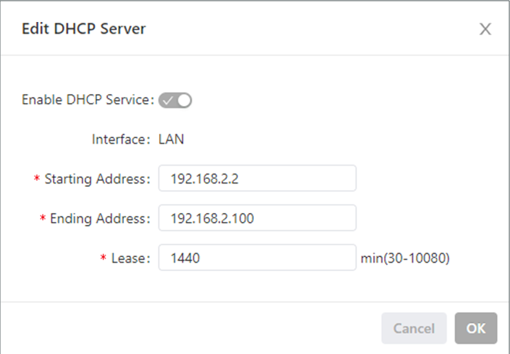
The DHCP server parameters are described as follows:
Enable DHCP Service: enables or disables the DHCP service.
Interface: LAN
Starting Address: specifies the start IP address of the IP address pool for address allocation to DHCP clients.
Ending Address: specifies the end IP address of the IP address pool for address allocation to DHCP clients.
Lease: specifies the validity period of allocated IP addresses. The DHCP server will reclaim the expired IP addresses for reallocation. This field cannot be left blank.
Windows Name Server (WINS): specifies the IP address of the WINS server.
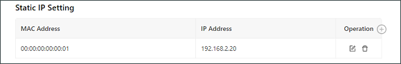
Static IP Setting: allows you to bind a fixed IP address to a MAC address, as shown in the following figure.
DNS
A domain name system (DNS) is a distributed database used for TCP/IP applications and provides translation between domain names and IP addresses. DNS allows users to access some applications by using easy-to- remember, meaningful domain names, which are then translated into the correct IP addresses by a DNS server on the network. You can configure a DNS server and the DNS relay service and view the configuration on
the DNS page.
Follow these steps to configure a DNS server:
Choose Network > Network Services > DNS to display the DNS page.
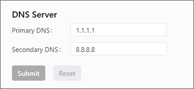
Enter the IP address of the DNS server.
Click Submit to apply the configuration. The following figure shows the DNS server configuration.
Follow these steps to configure the DNS relay service:
Choose Network > Network Services > DNS to display the DNS page.
Enable the DNS relay service. The DNS relay service cannot be disabled when the DHCP server feature is enabled.
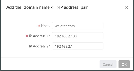
Click the Add icon to add a [domain name <=> IP address] pair.
Enter the domain name or IP address of a host and specify the matching IP address.
Click OK to save the configuration, and then click Submit to apply the configuration. The following figure shows the configuration of the DNS relay service.
Host List
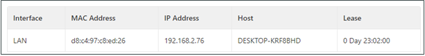
You can view information about hosts connected to the TK600 on the Host List page. Choose Network > Network Services > Host List to display the Host List page, as shown in the following figure.
Routing
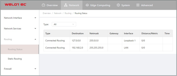
Routing Status
Choose Network > Routing > Routing Status to display the Routing Status page. This page displays information about static routes configured on the TK600, as shown in the following figure.
Static Routing
You can configure static routes on the Static Routing page. Then, packets sent to a specific destination are forwarded through the specified route. (Generally, you do not need to configure static routes.) Follow these steps to configure a static route:
Choose Network > Routing > Static Routing to display the Static Routing page.
Click the Add icon to add a static route.
Set the parameters.
Click OK to save the configuration, and then click Submit to apply the configuration.
The following figure shows the configuration of a static route.
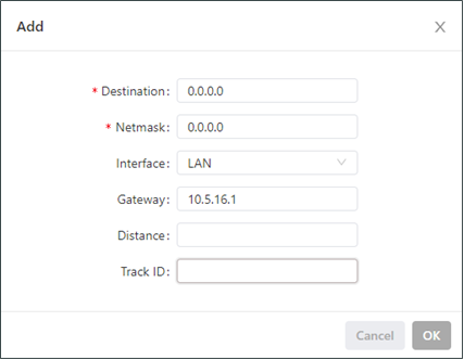
Parameters of a static route are described as follows:
Destination: specifies the destination IP address to which packets are sent.
Netmask: specifies the subnet mask of the destination IP address.
Interface: specifies the interface through which data packets are forwarded to the destination network.
Gateway: specifies the IP address of the next router that data packets pass through before reaching the destination IP address.
Distance: specifies the priority of the route. A smaller value indicates a higher priority.
Track ID: specifies the track index or ID.
Firewall
ACL
An access control list (ACL) permits or denies specified data flows (such as the data flow from a specified source IP address or account) based on a series of matching rules to filter the data reaching a network interface. You can configure a data filtering policy for a network interface on the ACL page. The configuration procedure is as follows:
Choose Network > Firewall > ACL to display the ACL page.
Click the Add icon under Access Control Policy to add an access control policy.
Set the parameters.
Click the Add or Edit icon under ACL to add an access control list on a specified interface.
Set the parameters.
Click OK to save the configuration, and then click Submit to apply the configuration.
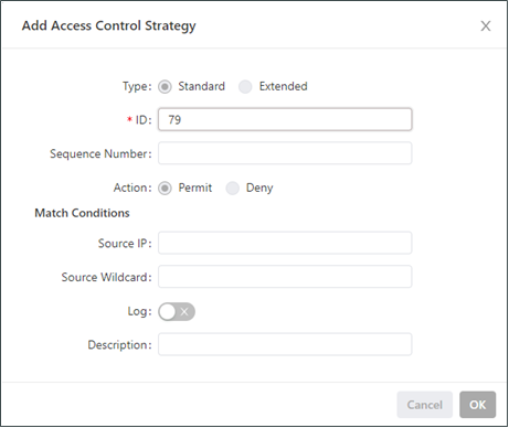
The following figure shows the configuration of a standard access control policy.
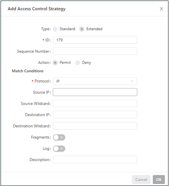
The following figure shows the configuration of an extended access control policy.
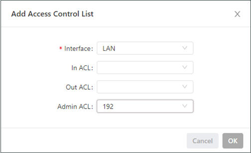
The following figure shows the configuration of an access control list.
Parameters of a standard access control policy are described as follows:
ID: specifies the ID of an ACL rule, in the range of 1-99. A smaller value indicates a higher priority of the rule.
Sequence Number: specifies the sequence number of the ACL rule. A smaller value indicates a higher priority of the rule.
Action: permits or denies forwarding of matching packets.
Source IP: specifies the source IP address of packets in the ACL rule. If this field is kept blank, the rule matches packets from all networks.
Source Wildcard: specifies the wildcard mask of the source IP address in the ACL rule.
Log: enables or disables recording of access control logs.
Description: records meanings of access control parameters.
Parameters of an extended access control policy are described as follows:
ID: specifies the ID of an ACL rule, in the range of 100-199. A smaller value indicates a higher priority of the rule.
Sequence Number: specifies the sequence number of the ACL rule. A smaller value indicates a higher priority of the rule.
Action: permits or denies forwarding of matching packets.
Protocol: specifies the access control protocol.
Source IP: specifies the source IP address of packets in the ACL rule. If this field is kept blank, the rule matches packets from all networks.
Source Wildcard: specifies the wildcard mask of the source IP address in the ACL rule.
Source Port: specifies the source port number of packets. The value any indicates that TCP/UDP packets with any source ports match the rule. This parameter is available only when the TCP or UDP protocol is selected.
Destination IP: specifies the destination IP address of packets in the ACL rule. If this field is kept blank, the rule matches packets destined for all networks.
Destination Wildcard: specifies the wildcard mask of the destination IP address in the ACL rule.
Destination Port: specifies the destination port number of packets. The value any indicates that TCP/UDP packets with any destination ports match the rule. This parameter is available only when the TCP or UDP protocol is selected.
Established Connection: specifies the range of TCP packets controlled. If this option is selected, the system controls TCP packets on established connections and does not control those on unestablished connections. If this option is deselected, the system controls TCP packets on both established and unestablished connections. This parameter is available only when the TCP protocol is selected.
Fragments: enables or disables control of fragmented data packets sent from the interface.
Log: enables or disables recording of access control logs.
Description: records meanings of access control parameters.
Parameters of an access control list are described as follows:
Interface: specifies the name of the interface on which the access control policy is configured.
Rule: specifies the inbound, outbound, and administrative rules.
NAT
Network address translation (NAT) allows multiple hosts in a LAN to connect to the Internet by using one or multiple public IP addresses. This feature maps a few public IP addresses to many private IP addresses to conserve public IP addresses. You can view and configure NAT rules on the NAT page. The configuration procedure is as follows:
Choose Network > Firewall > NAT to display the NAT page.
Select an interface from the Interface drop-down list.
Click the Add icon under Network Address Translation (NAT) Rules to add an NAT rule and set parameters for the rule.
Click OK to save the configuration, and then click Submit to apply the configuration. 5.
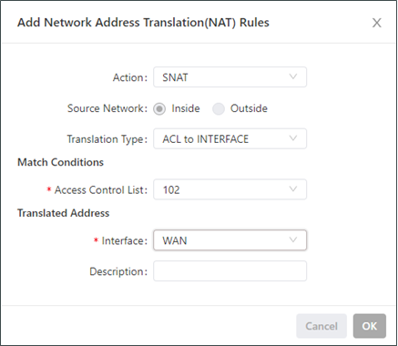
As shown in the following figure, the NAT rule allows hosts connected to the TK600 to connect to the Internet by using the IP address of interface WAN.
Parameters of the NAT rule are described as follows:
Action
SNAT: uses the source network address translation feature that translates source IP addresses of data packets into another IP address. Generally, this feature is used for data packets sent to the Internet through the router.
DNAT: uses the destination network address translation feature that translates destination IP addresses of data packets into another IP address. Generally, this feature is used for data packets sent to the private network through the router.
1:1NAT: uses one-to-one IP address translation.
Source Network (available when the action is set to SNAT or DNAT):
Inside: translates private IP addresses.
Outside: translates public IP addresses.
Translation Type, which can be:
IP to IP
IP to INTERFACE
IP PORT to IP PORT
ACL to INTERFACE
ACL to IP
Access Control List (unavailable for 1:1 NAT): specifies the ACL rule used to match the packets of which the IP addresses are translated.
Translated Address (unavailable for 1:1 NAT): specifies the IP address or interface translated from the source address.
Description: specifies the description of the NAT rule.
Edge Computing
Python Edge Computing
Install and run Python App
To install and run Python App in TK600, please refer to the following process, this document takes the Device Supervisor as an example (if you want own functionality please get in contact with your Welotec Sales):
Step 1: Install the App
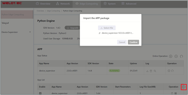
Before installing the App, you need to ensure that the Python Edge Computing Engine is enabled and the Python SDK is installed, as shown in the following figure:

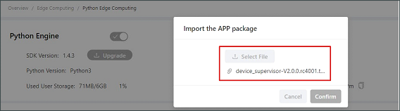
Choose Edge Computing > Python Edge Computing. click the Add button and select the App package file to be installed, then click Confirm
After importing, you can view the imported Apps, as shown in the following figure:
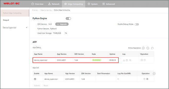
Step 2: Run the App Select enable App and click Submit.
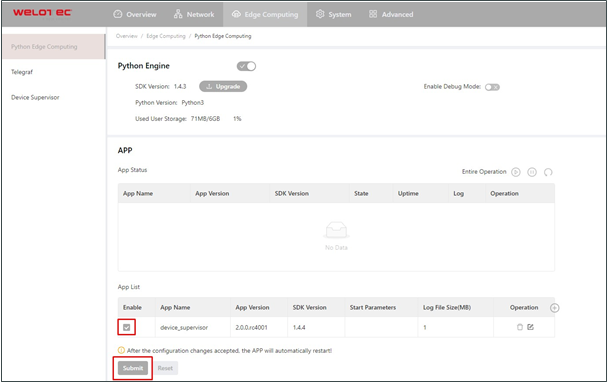
Once enabled, the App automatically runs and will run every time the TK600 is started.
Update Python App version
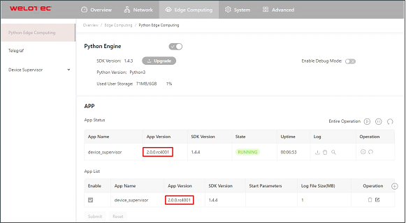
Generally, if you need to update the Python App version, you only need to import the new version of the App on the Edge Computing > Python Edge Computing page.
After the update is completed, as shown below:
Enable the Debug Mode
To run and debug Python code on TK600, you need to enable TK600’s debug mode. Choose Edge Computing > Python Edge Computing, select Enable Debug Mode.
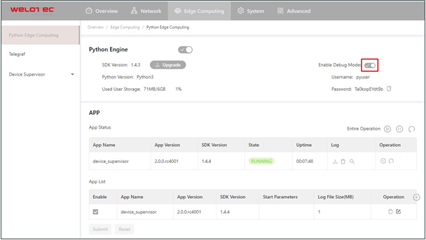
After the debugging mode is enabled, TK600 will start an SSH server to listen on port 222 of LAN (default IP address being 192.168.2.1). The username and password of the SSH server are displayed on the previous web page. A random password is generated every time the debugging mode is enabled or the TK600 is restarted to ensure security.
System
System Time
To enable the TK600 to cooperate with other devices properly, you may need to set an accurate system time for it. For this purpose, set the system time on the System Time page and enable the NTP protocol to implement clock synchronization among all clock-supporting devices on the network. In this way, all devices maintain the same clock to provide applications based on the consistent time. Follow these steps to set the system time:
Method 1: Select a time zone.
Choose System > System Time to display the System Time page.
Select the time zone where the TK600 is located from the Time Zone drop-down list.
Click Apply.
Method 2: Set the system time manually.
Choose System > System Time to display the System Time page.
Set a specific time in the Set Time field.
Click Apply.
Method 3: Use the local time of the PC.
Choose System > System Time to display the System Time page.
The TK600 can obtain the time of the PC as its local time.
Click Sync next to the Device Time field.
Method 4: Enable SNTP clients.
Choose System > System Time to display the System Time page.
Select Enable SNTP Clients.
Set the parameters.
Click Submit to apply the configuration.
System Logs
Choose System > Log to display the Log page. This page displays a large amount of information about the network and TK600, such as its running status and changes of configuration. On the Configure page, you can set a remote log server. Then, the TK600 will synchronize all system logs to the remote log server. The host used as the remote log server must run a remote log program.
Configuration Management
Choose System > Configuration Management to display the Configuration Management page. On this page, you can back up configuration parameters, import parameter settings, and restore factory settings of the TK600. These functions are described as follows:
Configuration Management
Auto Save: enables or disables automatic saving of modified configuration in the startup configuration file.
Encrypted: enables or disables password encryption. After this option is selected, all passwords configured on the TK600 web system are displayed in encrypted text. This feature improves the security of passwords.
Configuration Files Operations
Import Startup Config: allows you to import a configuration file as the startup configuration of the TK600. The TK600 will load the imported configuration file upon a reboot. Ensure the validity and correct order of commands in the imported configuration file. The TK600 filters out invalid commands in the imported configuration file, and then saves the valid commands as the startup configuration. The system will execute these commands sequentially after a reboot. If commands in the imported configuration file are not listed in a valid order, the system cannot enter the expected state after a reboot.
Export Startup Config: allows you to back up the startup configuration on a host. The startup configuration is the configuration that the TK600 loads after it starts.
Export Running Config: allows you to back up the running configuration on a host. The running configuration is the configuration that the TK600 is running.
Restore Factory Configuration: allows you to restore the factory settings of the TK600. This operation restores all parameters on the TK600 to the default settings. The factory settings are restored after a reboot of the TK600.
Firmware Upgrade
Follow these steps to upgrade the firmware version:
Choose System > Firmware Upgrade to display the Firmware Upgrade page.
Click Select File to select a firmware file for the TK600.
Click Starting Upgrade and OK to start the firmware upgrade.
Wait until the upgrade succeeds, and then click Reboot to restart the TK600.
Access Tools
To facilitate TK600 management and configuration, you can configure the TK600 management and access methods on the Access Tools page. Follow these steps to complete the configuration:
Configure HTTPS
Choose System > Access Tools to display the Access Tools page.
Select Enable HTTPS and set the parameters.
Click Submit to apply the configuration.
Configure Telnet
Choose System > Access Tools to display the Access Tools page.
Select Enable TELNET and set the parameters.
Click Submit to apply the configuration.
Configure SSH
Choose System > Access Tools to display the Access Tools page.
Select Enable SSH and set the parameters.
Click Submit to apply the configuration.
The following figure shows the configuration of HTTPS-based management.
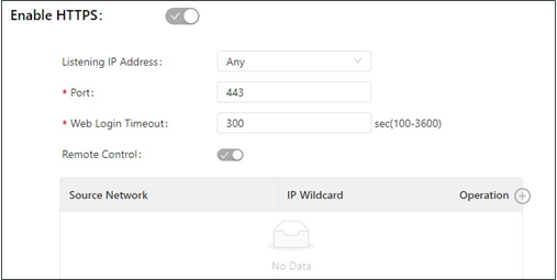
The HTTPS parameters are described as follows:
Listen IP Address: specifies the listening IP address. Options include Any, 127.0.0.1, and other IP addresses.
Port: specifies the listening port number of HTTPS.
Web Login Timeout: specifies the timeout period of web page login. The valid value range is 0-3600.
Remote Control: enables or disables remote access to the TK600 through HTTPS. If no remote control network is specified, the TK600 can be remotely controlled through any network.
The following figure shows the configuration of Telnet-based management.

The Telnet parameters are described as follows:
Listen IP Address: specifies the listening IP address. Options include Any, 127.0.0.1, and other IP addresses.
Port: specifies the listening port number of Telnet.
Remote Control: enables or disables remote access to the TK600 through Telnet. If no remote control network is specified, the TK600 can be remotely controlled through any network.
The following figure shows the configuration of SSH-based management.
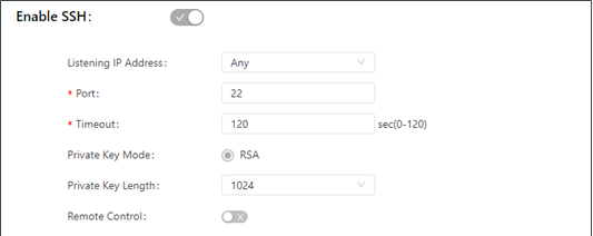
The SSH parameters are described as follows:
Listen IP Address: specifies the listening IP address. Options include Any, 127.0.0.1, and other IP addresses.
Port: specifies the listening port number of SSH.
Timeout: specifies the SSH timeout period. The valid value range is 0-120.
Key Mode: fixed as RSA.
Key Length: specifies the length of the key used. Options are 512, 1024, 2048, and 4096.
Remote Control: enables or disables remote access to the TK600 through Telnet. If no remote control network is specified, the TK600 can be remotely controlled through any network.
User Management
On the User Management page, you can add user accounts and manage the password and access rights of each account. These accounts allow multiple users to access and manage the TK600. Follow these steps to add a user:
Choose System > User Management to display the User Management page.
Click the Add icon to add a user.
Set the parameters.
Click OK to save the configuration.
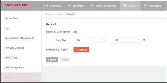
Reboot
Choose System > Reboot to display the Reboot page, and then reboot the TK600 or set a scheduled reboot plan for it. As shown in the following figure, the TK600 is configured to reboot on 0:00 every day.
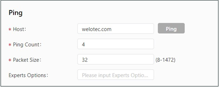
Network Tools
Choose System > Network Tools to display the Network Tools page. You can diagnose network problems of the TK600 on this page. You can enter some extension options in the Expert Options area. For example, expert option -t for the ping tool enables the TK600 to ping a specified host continuously until you stop the ping. The ping tool can be used to check whether a network is reachable. The following figure shows the configuration of a ping test.
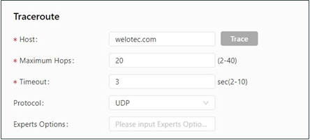
The traceroute tool can be used to determine the route used to transmit IP datagrams to a destination. The following figure shows the configuration of a traceroute test.
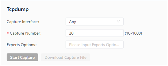
The Tcpdump tool can be used to capture packets transmitted on a specified interface. The following figure shows the Tcpdump configuration.
3rd Party Notification
Choose System > 3rd Party Notification to display the 3rd Party Notification page. You can view the statement about the third-party software used for the TK600.
Advanced
Some functions are not fully migrated yet from TK800 series to TK600 series. For advanced functions you can still use the TK800 webinterface.
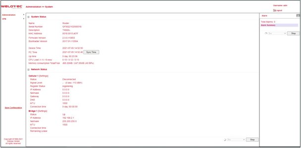
Administration
On this page, you can view the system status and network status (including the firmware version, MAC address, system time, and up time of the router).
VPN
OpenVPN
In the OpenVPN architecture, when a user accesses a remote virtual address (an address of a virtual NIC, not a real address), the operating system uses the routing mechanism to send the datagrams (TUN mode) or data frames (TAP mode) to the virtual NIC. When the service program receives the data, it processes the data and sends the data to the external network through the socket. When the remote service program receives the data from the external network through its socket, it processes the data and sends the data to the virtual NIC. The application software then receives the data. At this time, a unidirectional transmission process is completed. The reverse transmission process is similar.
OpenVPN Client
The parameters of an OpenVPN client are described as follows:
Enable: enables or disables the OpenVPN client.
Index: specifies a tunnel ID.
OpenVPN Server: specifies the IP address or domain name of an OpenVPN server.
Port: specifies the port number used to establish an OpenVPN tunnel.
Protocol Type: specifies the protocol used for data transmission. Options are UDP and TCP.
Authentication Type: Select an authentication type and set parameters for the authentication type.
Description: specifies the description of the OpenVPN tunnel.
Show Advanced Options
Source Interface: specifies the interface used to establish the OpenVPN tunnel.
Interface Type: specifies the type of data sent from the interface.
Tun: mostly used for IP-based communication.
Tap: allows complete Ethernet frames to pass through the OpenVPN tunnel and provides support for non-IP protocols.
Network Type: Options are net30, p2p, and subnet.
net30: Four IP addresses with a 30-bit mask are selected from the IP address pool. The larger one between the two intermediate IP addresses is used as the IP address of the client’s virtual NIC, and the smaller one is used as the peer IP address.
p2p: An IP address is selected from the IP address pool as the IP address of the client’s virtual NIC, and the actual IP address of the virtual NIC is used as the peer IP address.
Subnet: An IP address is selected from the IP address pool as the IP address of the client’s virtual NIC, and the subnet mask of the virtual NIC is used as the peer IP address.
Cipher: specifies the protocol used to encrypt the data transmitted over the OpenVPN tunnel. The setting must be the same on the client and server.
HMAC: specifies the authentication method used for data transmitted over the OpenVPN tunnel. Data cannot be transmitted if the authentication fails. The setting must be the same on the client and server.
Compression LZO: specifies the compression format of data transmitted over the OpenVPN tunnel.
Redirect-Gateway: enables the OpenVPN interface to act as the default gateway for the client, so that all traffic of the client is forwarded through the OpenVPN interface.
Remote Float: allows the remote device to change its IP address or port.
Link Detection Interval: specifies the interval for sending link detection packets after an OpenVPN tunnel is established. The valid value range is 10-1800, and the unit is second.
Link Detection Timeout: specifies the timeout period of OpenVPN link detection. After the number of link detection failures reaches the maximum value, the local device initiates a new L2TP connection. The valid value range is 60-3600.
MTU: specifies the maximum transmit unit on the OpenVPN interface, which is expressed in bytes.
Enable Debug: enables or disables debugging logs.
Expert Configuration: specifies OpenVPN extension parameters.
Import Configuration: Select the OpenVPN configuration file you want to import.
OpenVPN Server
The parameters of an OpenVPN server are described as follows:
Enable: enables or disables the OpenVPN server.
Config Mode: specifies whether to complete the configuration manually or import a configuration file.
Manual Config
Authentication Type: specifies the authentication method used.
Local IP Address: specifies the virtual IP address of the OpenVPN server interface.
Remote IP Address: specifies the virtual IP address of the OpenVPN client.
Description: specifies the description of the OpenVPN tunnel.
Show Advanced Options: enables or disables display of advanced options.
Source Interface: specifies the interface used to establish the OpenVPN tunnel.
Interface Type: specifies the type of data sent from the interface.
Tun: mostly used for IP-based communication.
Tap: allows complete Ethernet frames to pass through the OpenVPN tunnel and provides support for non-IP protocols.
Network Type: Options are net30, p2p, and subnet.
Protocol Type: specifies the communication protocol used between the client and server. The setting must be the same on the client and server.
Port: specifies the port number of the OpenVPN service.
Cipher: specifies the protocol used to encrypt the data transmitted over the OpenVPN tunnel. The setting must be the same on the client and server.
HMAC: specifies the authentication method used for data transmitted over the OpenVPN tunnel. Data cannot be transmitted if the authentication fails. The setting must be the same on the client and server.
Compression LZO: specifies the compression format of data transmitted over the OpenVPN tunnel. The setting must be the same as that on the client.
Link Detection Interval: specifies the interval for sending link detection packets after an OpenVPN tunnel is established. The valid value range is 10-1800, and the unit is second.
Link Detection Timeout: specifies the timeout period of OpenVPN link detection. If the local device does not receive a response to the link detection packet within this period, link detection fails. The valid value range is 60-3600.
MTU: specifies the maximum transmit unit on the OpenVPN interface, which is expressed in bytes.
Enable Debug: enables or disables debugging logs.
Expert Configuration: specifies OpenVPN extension parameters.
Username/Password: specifies the user name and password used for server access when password authentication is used.
Certificate Management
The Simple Certificate Enrollment Protocol (SCEP) is a certificate management protocol formulated jointly by Cisco and Verisign. This protocol combines PKCS#7 and PKCS#10 standards, and supports extensive clients and certification authorities (CAs).The certification management parameters are described as follows:
Enable SCEP: enables or disables the Simple Certificate Enrollment Protocol.
Force to re-enroll: restarts the certificate enrollment service every time without checking the status of the current certificate.
Status: displays the current certificate enrollment status on the device, which can be Initiation, Enrolling, Re-Enrolling, or Complete.
Protect Key: specifies the key set during certificate enrollment for encryption of the digital certificate. You can import or export a certificate only after entering the protection key set during certificate enrollment.
Protect Key Confirm: Enter the protection key again to confirm the key.
Strict CA: sets the ID of a trusted CA. The certificate of a device is enrolled and issued by a trusted CA. Therefore, you must specify the ID of a trusted CA to bind the device to the CA. Then, the device completes certificate application, acquisition, revocation, and query through this CA.
Server URL: specifies the URL of the CA server. You must specify a CA server URL beforehand, so that the device can apply to this server for a certificate through SCEP, for example, http://100.17.145.158:8080/certsrv/mscep/mscep.dll.
Common Name: specifies the general name of the certificate required.
FQDN: specifies the fully qualified domain name (FQDN) of the certificate. FQDN is the unique identifier of an entity on a network and is composed of a host name and a domain name. It can be resolved into an IP address. For example, host name www and domain name whatever.com form an FQDN [www.whatever.com.]
Unit 1: specifies the name of the first organization of the certificate.
Unit 2: specifies the name of the second organization of the certificate.
Domain: specifies the qualified domain name of the certificate.
Serial Number: specifies the serial number of the certificate.
Challenge: specifies the challenge code of the certificate, which is required for certificate revocation (optional).
Challenge Confirm: Enter the challenge code again to confirm the setting.
Unstructured address: specifies the IP address of the certificate.
RSA Key Length: specifies the length of the RSA key. The valid value range is 128-2048, and the unit is bit.
Poll Interval: specifies the interval at which the device queries the current certificate status from the server. The valid value range is 30-3600, and the unit is second.
Poll Timeout: specifies the maximum duration for querying the certificate status. The device considers the certificate application fails when the timeout period expires. The valid value range is 30-86400, and the unit is second.
Revocation: enables or disables certificate revocation.
CRL URL: specifies the URL of the certificate revocation list (CRL) distribution point.
OCSP URL: specifies the URL of the Online Certificate Status Protocol (OCSP) server. Generally, it is the same as the URL of the CA server.
Note: When using a certificate, ensure that the system time is consistent with the actual time.